Title here
Summary here
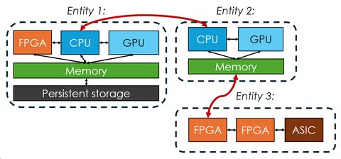
A system graph is the heart of Adaptyst. It describes how your computer system is structured or (in the future) how you want it to be structured. It is also an essential part of the Adaptyst flow: the tool will not run without providing a system graph definition file.
The graph consists of nodes and entities: nodes can be imagined as computer peripherals (such as CPUs, GPUs, FPGAs, TPUs, NICs etc.) while entities are groups of nodes and can be imagined as computer servers or separate computers. Edges between nodes and entities represent connections between the components/computers and are directed. For example, an edge from a CPU to a GPU can indicate data transfer from a CPU to a GPU, but not the other way round.
It is important to note the special role entities play in the Adaptyst flow: each entity is responsible for handling the workflow execution if needed (e.g. in order to do profiling of it). This can happen in one of the four ways:
Supported number of entities
The current version of Adaptyst supports having only one entity in the local Adaptyst-handled mode. This will change in the future.
Each node and edge can have one or more modules attached to it. The modules are set up for both Adaptyst and Adaptyst Analyser and are responsible for modelling/profiling their system components or connections between them and providing information of interest to an end user (e.g. profiling results). For example, a CPU node can have three modules attached to it: one for profiling walltime of a workflow, one for modelling cache behaviours caused by the workflow, and one for profiling speculative execution. Furthermore, there are no limits related to the granularity of a system graph: a node can represent either a component as a whole or just a part of it.
In order to use Adaptyst, at least one module must be installed.
You can set up an unlimited number of modules from both the Adaptyst team and the outside world (however, modules may have limits on how many of its instances can be present in an entity). They come in two parts: one for Adaptyst and one for Adaptyst Analyser. Each of these is installed in a different way:
Adaptyst: Unless the tool has been compiled with different settings or run with a different
value of the ADAPTYST_MODULE_DIRS environment variable, all modules must be installed into
<your install prefix>/opt/adaptyst/modules.
There is no dedicated utility in Adaptyst for setting up modules: you need to follow the installation guide provided by their developers.
Adaptyst Analyser: A module should be installed via adaptyst-analyser. Just run
adaptyst-analyser <path to the Adaptyst Analyser module directory>.
A starting point here can be e.g. the linuxperf module created by the Adaptyst team. Its installation instructions and documentation can be found here.
System graphs are defined in text files following the YAML syntax:YAML reference
# The YAML map of entities in a system graph
entities:
  # The name of an entity and the YAML map of it
  entity1:
    # Entity options
    options:
      # COMPULSORY: The workflow execution
      # handling mode of an entity. It can be either:
      # * "local": local Adaptyst-handled
      # * "custom": local node-handled
      # * "remote": remote Adaptyst-handled
      # * "custom_remote": remote node-handled
      #
      # WARNING: The current version of Adaptyst
      # supports "local" only!
      handle_mode: local
      # Optional: The number of threads
      # isolated for profiling/processing/... done by
      # modules in an entity (this value may be
      # ignored by a module)
      processing_threads: 3
    # The YAML map of nodes within an entity
    nodes:
      # The name of a node and the YAML map of it
      node1:
        # Whether a node is a directing node. Ignored and
        # therefore optional when handle_mode is "local" or
        # "remote".
        directing: false
        # The list of modules attached to a node
        modules:
          # Each entry has at least the name of a module
          # as installed and the optional YAML map of module
          # options
          - name: abc
            options:
              option1: value1
              option2: value2
              option3: value3
          - name: def
            # If a node is designated as directing,
            # all modules can assert "directing node"
            # responsibilities. This may lead to conflicts
            # between modules. To avoid this scenario,
            # it is possible to make a specific module
            # never see that its node is a directing one.
            # To do this, set "never_directing" to true.
            # Otherwise, set it to false or do not
            # set it at all as this setting is optional.
            never_directing: true
            options:
              option1: value1
      node2:
        modules:
          - name: xyz
          - name: ghi
            options:
              option1: value1
              option2: value2
    # The YAML map of edges within an entity
    edges:
        # The name of an edge and the YAML map of it
        edge1:
            # The name of a node within the entity where
            # the start point is
            from: node1
            # The name of a node within the entity where
            # the end point is
            to: node2
            # The optional list of modules attached to
            # an edge (the structure is the same as
            # for nodes except for the never_directing
            # setting which is not applicable to edges)
            #
            # NOTE: This is NOT supported by the current
            # version of Adaptyst and will be thus
            # ignored!
            modules:
              - name: jkl
                options:
                  option1: value1

# The YAML map of inter-entity edges in a system graph
# (this is for reference, it will be supported in the
# future versions of Adaptyst, the current version
# ignores this)
edges:
  # The name of an edge and the YAML map of it
  edge1:
    # The YAML map defining the start point of an edge
    from:
      # The name of an entity where the start point is
      entity: entity1
      # The name of a node within the entity where the
      # start point is
      node: node1
      # The optional list of modules attached to
      # the start point of an edge (the structure
      # is the same as for nodes except for the
      # never_directing setting which is not applicable
      # to edges).
      #
      # This is different than attaching
      # a module to a node: modules are attached to
      # both ends of an edge in two different entities
      # and they are told that they are attached to
      # an edge rather than a node. Handling is done by
      # an entity where the start point is.
      modules:
        - name: jkl
        - options:
            option1: value1
    # The YAML map defining the end point of an edge
    # (the structure is the same as for the start point)
    to:
      entity: entity2
      node: node1
      modules:
        - name: jkl
        - options:
            option1: value1
  edge2:
    from:
      entity: entity2
      node: node1
    to:
      entity: entity1
      node: node1
Current system graph support
Adaptyst supports defining system graphs manually only at the moment, with no room for automatic component detection or matching. Stay tuned for future updates though!
As you may see, a module can be configured in a specific way using options made available by its developer. See the documentation of a module for more information (it may even be the case that a module doesn’t have any options!).
The simplest system graph is a single node representing a CPU with the linuxperf
module attached to it:YAML example
entities:
  entity1:
    options:
      handle_mode: local
    nodes:
      cpu:
        modules:
          - name: linuxperf
As mentioned in other parts of the documentation, Adaptyst will eventually be able to determine automatically the best set of software, system, and hardware optimisations to maximise performance for a given compute workflow and user requirements. Because it is important to maintain use case flexibility at the same time (given that it is rare that a user is able to freely assemble completely custom systems and hardware), partial system graphs will play a key role here: compared to standard system graphs, they will allow some uncertainty in a choice of system/hardware components.
The example is shown in the figure below. In this case, the only thing which is 100% certain and unchangeable is that a GPU will be deployed. For other parts, Adaptyst will need to both determine whether CPU 1 or CPU 2 should be used and whether a custom accelerator should be deployed. The tool will also decide which parts of a compute workflow should go to the CPU, the GPU, or the accelerator.
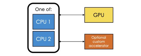
A user will obviously be able to use a standard system graph as well: Adaptyst will interpret it as “the system graph is fixed and no optimisations in terms of hardware/system choices can be made”. This doesn’t preclude system/hardware customisations inside connections/nodes to the extent allowed by modules attached to the system graph.